4. Visible Issues
This section addresses issues that you encounter with your data that are not specifically flagged by an error dialog.
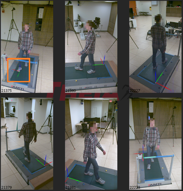
4.1. Coordinate system is out of place in one camera view.
Explanation
If the coordinate system is out of place in one camera view, but is positioned and oriented as expected in the remainder of the views, it is likely that the position of the single camera changed between the recording of the calibration trial and the loaded movement trial. The camera view may have been intentionally changed, as in the case of adjusting a camera view to better capture the volume, or it may have been accidentally changed, in the case of a tripod being bumped by a passerby.
Possible Solutions
Use a different calibration from the same session.
If multiple calibration trials were recorded during the data collection, try loading one of the other calibration files. If any of the other calibrations were recorded after the camera was moved, they should be able to properly calibrate the camera system. This is the best possible solution, and follows our recommendation to record at least two calibration trials per data collection (one at the start, one at the end).
If possible, collect a new calibration trial.
If the cameras have not been moved since the movement trial was recorded, the next best solution is to record a new calibration trial with the cameras in their current position and orientation. This calibration trial can then be processed and assigned to the movement trial, allowing the camera system to be calibrated properly.
Exclude the moved camera view.
If it is no longer possible to record an additional calibration trial (i.e. the camera system has been taken down), the camera that was moved can be excluded from the analysis using the Toggle Views tool under the Tools dropdown menu. Provided that the camera system consists of at least seven cameras and only one camera was moved, this will allow the movement trial to be processed using all properly calibrated camera views, preventing a total loss of the trial. Be sure to use the Toggle Views tool before running the analysis in order to exclude the affected camera view.
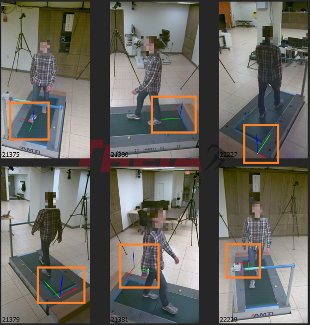
4.2. Coordinate system is in different positions and/or orientations in all camera views.
Explanation
If the global coordinate system is in different positions and/or orientations in each of the camera views, this indicates that an incorrect calibration file was loaded. If the loaded calibration file has camera IDs that match those for the loaded videos but the calibration corresponds to a different camera setup, the calibration file can still be loaded successfully. However, this will lead to the camera system being incorrectly calibrated and the global coordinate system will not appear in the location or orientation that is expected for the loaded video data. If this issue goes unnoticed and the trial is then processed, it will lead to the Track People Incomplete error dialog.
Possible Solutions
Confirm the correct calibration was loaded. Double check that you loaded the correct calibration file for the camera setup used to record the loaded video data. This calibration file should have been saved after processing the calibration trial recorded during the same collection session as the loaded movement data.
4.3. Coordinate system is in an incorrect but consistent position and/or orientation in all camera views.
Explanation
If the global coordinate system is in an incorrect but consistent position and/or orientation in all camera views, this typically indicates that a different frame was used to set the origin than what was selected in the Chessboard Calibration dialog. This is often caused by the chessboard or its blue squares not being sufficiently visible in the selected Origin Frame, which can be a result of the chessboard being too far from the cameras, challenging lighting conditions, or the cameras being parallel with the surface of the chessboard. In this case, Theia3D searches for the nearest frame in which the chessboard is adequately detected for localization, and uses that frame instead, which can lead to a floating global coordinate system in an undesirable position and orientation.
Possible Solutions
Use the Enhance Videos tool to improve chessboard visibility.
One approach is the use the Enhance Videos tool to adjust the brightness, contrast, and white balance of the videos in an effort to improve the visibility of the chessboard in the desired origin frame. Use the Blue Mask tool to check if the blue squares are visible in the desired origin frame, and adjust the enhancement settings to improve their visibility. After enhancing the videos, reprocess the calibration trial.
Use the Adjust Origin option within the Object Calibration tool to manually annotate the chessboard in the desired origin position to set the global coordinate system. To use this approach, open the Object Calibration tool and use Load Object to load a .csv file containing 3D points for the chessboard pattern, or use the Add button to add these points directly. When using a standard Theia Markerless chessboard with 100 millimeter squares, the 3D points that describe the inner corners of the outside corner squares are: (0,0,0), (0,600,0), (300,600,0), and (300,0,0). With the chessboard object points loaded or created, double click on a view where these points are the most visible. While holding control, manually select these positions (i.e. the inner corners of the outer chessboard squares) in this view by carefully clicking on their location. When complete, repeat this process for a total of three or more camera views, then click Adjust Origin. This will maintain the relative positions and orientations of the cameras from the automatic calibration, but will move the reference frame to the correct location.
3. Use the Adjust Calibration tool to manually move and re-orient the global coordinate system. The Adjust Calibration tool under the Calibration dropdown menu can be used to modify the position and orientation of the global reference frame, relative to its original position. Use the x, y, and z sliders under the Position and Angle sections to translate and rotate the global coordinate system about those axes of the original global coordinate system. After modifying the global coordinate system as desired, choose Apply or Apply and Save to save the adjusted calibration as a new .txt file.
Use a different origin frame and adjust the chessboard calibration settings (Normal Axis, Long Axis).
Another option to produce a more useful origin is to select a different origin frame and use the Normal Axis and Long Axis values in the Chessboard Calibration dialog to modify the orientation of the global coordinate system relative to the chessboard during the new origin frame selection. For example, selecting a video frame in which the chessboard is positioned vertically standing on its long edge, setting Normal Axis to X, and Long Axis to Y would produce a vertical upwards Z axis and may produce a more useful origin.
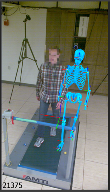
4.4. Skeleton is consistently outside the body.
Explanation
The most common reason for the projected 3D skeleton (or 3D body segments) to be consistently outside the body in the 2D videos is that there is an issue with the calibration file. The calibration of the camera system determines how the calculated 3D pose, represented by the 3D skeleton or 3D segments, is projected onto the 2D videos. Therefore, if there is an issue with the calibration file the 3D skeleton can be projected incorrectly onto the 2D videos, resulting in the skeleton or body segments appearing outside of the body.
Possible Solutions
To confirm that the calibration file is the issue, take note of whether the global coordinate system is positioned and oriented as expected in the camera view(s) for which the projected skeleton is outside the body. If the global coordinate system is not positioned correctly in one or more camera views, this confirms the issue is with the calibration file. Having confirmed the calibration file is the issue, please review the appropriate troubleshooting section for coordinate system issues.
4.5. Skeleton is momentarily incorrect.
Explanation
There are several reasons why the projected 3D skeleton or body segments may appear to be incorrect when reviewing a processed movement trial:
The GCVSPL Cutoff Frequency is too low for the movement.
If the GCVSPL Cutoff Frequency is set too low for the movement contained in the videos, the filtered pose may be underfitting the movement and can cause the skeleton to be momentarily incorrect relative to the videos. This can show up as excessively smooth skeleton movements that do not fully capture the movements in the videos.
The intrinsic lens calibration is inadequate.
If the intrinsic lens calibration of your cameras provides relatively low coverage of the camera views or insufficient variation in chessboard angle during the lens calibration trial, it may not adequately adjust for lens distortion or other lens effects. This can result in non-linearities in the camera view(s), which can manifest as warping of the image around the outside of the camera view(s). If the skeleton is momentarily incorrect when the subject approaches the edges of one or more camera views, and/or the skeleton tracking gets worse the closer they are to the border of the camera view, then an inadequate lens calibration may be the cause.
The extrinsic chessboard calibration is inadequate.
If the extrinsic calibration of your cameras has relatively high calibration error metrics (RMSE Diagonal, RMSE Angle), it may not provide reliable 3D reconstruction of predicted key points from the 2D camera views. This can result in the projected skeleton ‘drifting’ away from the participant as they move away from the calibrated capture volume origin. This drift can be further exacerbated by inadequate intrinsic lens calibration, which may further reduce the accuracy of the 3D projection when the subject nears the edges of the camera view(s). If the skeleton is momentarily incorrect when the subject moves away from the calibrated capture volume origin, an inadequate extrinsic calibration and/or intrinsic calibration may be the cause(s).
The participant’s body is not sufficiently visible for reliable construction.
If the participant being tracked is momentarily occluded or contorted in such a way as to significantly reduce the visibility of one or more body segments, the keypoint detections and projected 3D reconstruction can become temporarily incorrect. This generally manifests as obviously incorrect reconstruction of the participant’s skeleton such as impossible body segment poses or movements, but it can also appear as believable movements that visibly disagree with the videos. If the momentarily incorrect body segment(s) are not clearly visible in three or more camera views when the tracking is incorrect, the visibility (or lack thereof) of the body segment may be the cause.
(OptiTrack Prime Color cameras) Frames dropped by the camera hardware were filled in using Dropped Frames: Last Frame.
If there were any camera hardware issues that led to video frames being dropped during the recording of the trial, and the export setting Dropped Frames: Last Frames was used, the videos from cameras with dropped frames will have repeated identical frames for some duration of the video. That is, some videos may show the scene as perfectly stationary while the videos from other cameras that did not suffer dropped frames continue showing the movement. In this case, the person is usually tracked accurately based on the cameras without dropped frames, but the 3D reconstruction of the person’s movement will not align with the person in the videos with dropped frames. This is not incorrect tracking, but rather demonstrates the movement was tracked properly despite the videos showing the person at different instances in time.
Possible Solutions
Some possible solutions to momentarily incorrect skeleton tracking are as follows:
Increase the GCVSPL Cutoff Frequency.
If the skeleton movement appears excessively smooth and is not fully capturing the movements in the video, try increasing the GCVSPL Cutoff Frequency to reduce the effect of the filter and allow the movement to be tracked more accurately. After adjusting the GCVSPL Cutoff Frequency in the Preferences window, you only need to run the Solve Skeleton analysis step to view the updated pose results.
Reprocess the lens and chessboard calibration trials.
If the cause of the issue was an inadequate lens or chessboard calibration, the best approach is to reprocess both calibrations in an effort to improve their reults. Reprocess the lens calibration trial before reprocessing the chessboard calibration. Try using the Enhance Videos tool to improve the brightness, contrast, or white balance of the videos, or decreasing the Frame Grab Step value to increase the number of frames used to calibrate the lenses and camera system. After reprocessing the lens and chessboard calibrations, reprocess the movement
Record a new chessboard calibration trial.
If the results of the chessboard calibration trial are relatively low and you have tried enhancing the videos and adjusting the Frame Grab Step, you may need to record a new chessboard calibration trial, if possible.
Record a new lens calibration trial.
If the results of the lens calibration trial are relatively low and you have tried enhancing the videos and adjusting the Frame Grab Step, you may need to record a new lens calibration trial. This necessitates removing the cameras from the capture volume, and is therefore a more significant undertaking that will also require a new chessboard to be recorded after the cameras are returned to their setup.
4.6. Skeleton is incomplete.
Explanation
In general, the 3D skeleton appears to be incomplete when one independent part of the kinematic chain cannot be tracked. The body parts that are able to disappear will depend on the joint constraints you have selected in the Analysis section of the Preferences window, and the cause of their disappearance can vary.
For example, when Enable Free Arms is not selected, the shoulder joint is modelled with 3 degrees of freedom (DOF), allowing full rotational freedom but no translation of the upper arm relative to the torso. Therefore, if one of the arms cannot be tracked, then the entire left arm + torso + right arm chain will disappear. However, if Enable Free Arms is selected the shoulder joint is modelled with 6 DOF, allowing the arms to be tracked independently of the torso. This allows any of the left arm/torso/right arm segments to be tracked, even if one of the other segments cannot be tracked.
There are several reasons why a body segment may disappear in a processed movement trial:
The GCVSPL Cutoff Frequency is set too low.
If the GCVSPL Cutoff Frequency is set too low, it is possible for the moving body part(s) to be detected as an outlier and excluded from the tracking. This typically occurs when the movement is very fast and the GCVSPL Cutoff Frequency is set relatively low.
The body segment is not sufficiently visible to be tracked reliably.
If the body segment is occluded or otherwise difficult to discern in the videos due to poor lighting, dark clothing, a challenging pose, or other factors, it may not be possible to track the segment reliably and it will disappear.
Possible Solutions
Some possible solutions for incomplete skeleton tracking are as follows:
Increase the GCVPLS Cutoff Frequency.
If the cause of the incomplete skeleton is a low GCVSPL Cutoff Frequency resulting in the body segment being detected as an outlier, try increasing the GCVSPL Cutoff Frequency to allow the movement to be tracked. After adjusting the GCVSPL Cutoff Frequency in the Preferences window, you only need to run the Solve Skeleton analysis step to view the updated pose results.
Use the Enhance Videos tool to improve the video quality.
If the videos are too dark or not properly white-balanced, they may be improved using the Enhance Videos tool. This can improve the visibility of body segments and improve tracking quality. After adjusting these settings, you will need to use the Run Analysis button to perform all analysis steps.
Improve the quality of the data recorded by your camera system.
If the data quality is insufficient to be able to clearly see all body segments, try improving the quality of the data collected by your camera system. You may need to make adjustments such as increasing the amount of ambient light, increasing the camera resolution, selecting appropriate frame rate and exposure settings, or moving the cameras closer to the participant to capture them with higher resolution.
4.7. Skeleton is completely missing.
Explanation
There are a few reasons why the skeleton may be completely missing when reviewing a processed movement trial:
The Show Skeleton display option is deselected.
If the Show Skeleton option is not selected, the 3D skeleton reconstruction will not be displayed on the 2D videos.
The GCVSPL Cutoff Frequency is set too low for the movement.
If the GCVSPL Cutoff Frequency is set too low, it is possible for the moving body to be detected as an outlier and excluded from the tracking. This typically occurs when the movement is very fast and the GCVSPL Cutoff Frequency is set relatively low.
The person is not tracked.
If the Max People setting in the Preferences window is set to an integer value (i.e. not No Max) and there are other people who are more visible in the videos, the main person of interest may not be tracked and they will not have a skeleton.
The person is not sufficiently visible to be tracked.
If the person is not sufficiently visible in 3 or more cameras due to the camera positioning, orientation, or the quality of the video images, they may not be tracked.
Possible Solutions
Some possible solutions corresponding to the above causes for a completely missing skeleton are as follows:
Select Show Skeleton display option.
Select the Show Skeleton display option in the Display dropdown menu.
Increase the GCVSPL Cutoff Frequency.
If the cause of the missing skeleton is a low GCVSPL Cutoff Frequency resulting in the entire body being detected as an outlier, try increasing the GCVSPL Cutoff Frequency to allow the movement to be tracked. After adjusting the GCVSPL Cutoff Frequency in the Preferences window, you only need to run the Solve Skeleton analysis step to view the updated pose results.
Set the Max People setting to No Max.
If the person of interest was not tracked but other people within the videos were, set the Max People setting to No Max to ensure the person of interest is also tracked. After modifying this setting, you only need to run the Run Analysis (without 2D) analysis option to view the updated results.
Adjust the camera system setup or move the person to a more visible location within the volume.
If the person is not sufficiently visible to be tracked in the videos, the camera system setup and settings will need to be adjusted to improve the visibility of the person. You may need to move the participant within the capture volume, move or reorient your cameras, or adjust your camera settings to improve the visibility of the participant.
4.8. Skeleton is jittery.
Explanation
There are a few reasons why the skeleton may appear to be jittery when reviewing a processed movement trial:
The GCVSPL Cutoff Frequency is too high.
If the movement is somewhat slow and the GCVSPL Cutoff Frequency is set to a relatively high value, the filter will not be effect in reducing noise in the pose estimations, resulting in noise or jitter in the skeleton.
The person or body segment is not sufficiently visible.
If the person or their body segments are marginally visible, the pose estimates may be unstable resulting in noise or jitter in the skeleton. This can be a result of low resolution, low light, high levels of noise in the video images, and/or challenging clothing/background combinations.
Possible Solutions
Some possible solutions for the above causes of a jittery skeleton include:
Reduce the GCVSPL Cutoff Frequency.
If the skeleton jitter is due to a relatively high GCVSPL Cutoff Frequency being used for a slow movement, the jitter may be reduced by using a lower GCVSPL Cutoff Frequency. After adjusting the GCVSPL Cutoff Frequency in the Preferences window, you only need to run the Solve Skeleton analysis step to view the updated pose results.
Use the Enhance Videos tool to improve the video quality.
If the videos are too dark or not properly white-balanced, they may be improved using the Enhance Videos tool. This can improve the visibility of body segments and improve tracking quality. After adjusting these settings, you will need to use the Run Analysis button to perform all analysis steps.
Adjust the camera system setup to improve participant visibility.
If the person is not sufficiently visible to be tracked in the videos, the camera system setup and settings will need to be adjusted to improve the visibility of the person. You may need to move the participant within the capture volume, move or reorient your cameras, or adjust your camera settings to improve the visibility of the participant.